
Principle, Advantages and Possible Applications of the Slipform Method
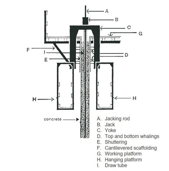
The slipform method for rising concrete structures with constant wall thickness has been in use for more than 30 years; it may be assumed that this method needs no introduction, as it has already been described in numerous publications. The basic elements of the typical slipform system are shown in the adjacent cross-sectional diagram.
Jacking rod A is located centrally in the concrete wall. Jack B slides upwards on A, taking yoke C with it. The following are attached to C: top and bottom whaling D with shuttering E, external platform F, working platform G and hanging platform H. A draw tube I is suspended centrally under yoke C so that, on completion of the wall, jacking rod A can be withdrawn and used again. The hanging platform H permits trowelling of the concrete surfaces during sliding as well as the laying bare of projecting reinforcements and the stripping of supports, etc.
On the IGA system, raising of the shuttering is effected by means of the double-acting rams B, which work in unison and feature a lifting capacity of 6-9.5 tons.
Attachment and lifting of the 28 mm dia. jacking rod (A) are effected by a simple rugged and reliably operating gripper head mechanism, which was developed and patented by IGA.
In comparison with the familiar methods employed hitherto, this system affords the following important advantages: simple, rapid exchange of the grippers while slipforming continues, on-the-spot up-and-down movement of the shuttering during unforeseen stoppages in concreting, short duration of sliding phases between placing of the individual concrete lifts and reinforcing steel, thanks to fully hydraulic actuation of the jacks for both advance and return movement combined with fully electromagnetic control. With appropriate selection of the concrete composition, the wall surfaces are rendered watertight.
Up to 100 jacks, arranged as shown in the adjacent schematic diagrams, are connected to a fully automatic, electromagnetically controlled pump unit.